GHA-15: Difference between revisions
Jump to navigation
Jump to search
m (→Notepad) |
m (→Threads) |
||
| (17 intermediate revisions by the same user not shown) | |||
| Line 1: | Line 1: | ||
= Garmin GHA-15 Radar Altimeter = | = Garmin GHA-15 Radar Altimeter = | ||
==== Intro ==== | |||
* The Garmin GHA-15 radar altimeter starts reporting altitude somewhere between 300 and 550 ft.<br>Note: the 500 ft announcement is GPS altitude based, 300 ft and lower is then radar altimeter based. | |||
* It transmits at 24 GHz with very low power (milliwatts) compared to COM radios and transponders (20 / 150 Watts). 24 GHz is not the controversial frequency that has interference issues with cell towers. | |||
* It needs very little power and the connector accepts 22 AWG wire or thinner (you can transition to a 22 AWG lead wire near the connector if you want to run a thicker wire). | |||
==== Videos ==== | ==== Videos ==== | ||
* [https://www.youtube.com/watch?v=c_1KuhIFVjQ RV12 Driver's Installation] | * [https://www.youtube.com/watch?v=c_1KuhIFVjQ RV12 Driver's Installation] | ||
| Line 7: | Line 12: | ||
* [https://vansairforce.net/community/showthread.php?t=218681 VAF] | * [https://vansairforce.net/community/showthread.php?t=218681 VAF] | ||
* [https://www.facebook.com/groups/vansrv10/posts/6340273269427052 FB] | * [https://www.facebook.com/groups/vansrv10/posts/6340273269427052 FB] | ||
* [https://www.facebook.com/groups/vansrv10/posts/6997949003659472 FB] | |||
==== Installation Manual ==== | ==== Installation Manual ==== | ||
| Line 12: | Line 18: | ||
---- | ---- | ||
==== Notepad ==== | ==== Notepad ==== | ||
[[File:Screen Shot 2023-10-21 at 4.03.53 PM.png|400x400px]]<br>Connector | [[File:Screen Shot 2023-10-21 at 4.03.53 PM.png|400x400px]]<br>Connector | ||
* Note: unlike with D-Sub connectors, each pin needs at least 5/8 inch of plain wire (22 AWG or thinner) before thickening up for example for a splice or shielding. The distance between the end of the pin and where the wire exists the rubber gasket through a tiny hole is quite long. | |||
* Note: on the rubbery back side of the connector, the printed "1" seems to be closer to the hole to the left of the "1", but pin 1 is to the right of the "1".<br>The center pin 22 is a bit off-center to the bottom. Together with hole straight below it, they constitute the vertical center axis of the connector. At the two circles above, the center axis splits between 21/15 and 14/1. At the outermost circle at the bottom, it splits between 7/8. The 4 holes above 22 are almost in a perfect square pattern.<br>[[File:Screen Shot 2023-10-22 at 10.47.20 PM.png|300x300px]]<br>On the (hard) back-end of the connector, the numbers are printed in a way that the "1" is actually closer to pin "1".<br>[[File:Screen Shot 2023-10-21 at 3.36.20 PM.png|331x331px]]<br>(as seen from the back of the connector where you insert the pins through the silicone seals. The 9 o-clock position of this connector points forward in direction of flight.) | |||
==== Screw Torque ==== | ==== Screw Torque ==== | ||
| Line 22: | Line 30: | ||
* 4 x 10-32 nut plates, e.g. [https://www.aircraftspruce.com/catalog/pnpages/K1000-3.php K1000-3 / MS21047L3] | * 4 x 10-32 nut plates, e.g. [https://www.aircraftspruce.com/catalog/pnpages/K1000-3.php K1000-3 / MS21047L3] | ||
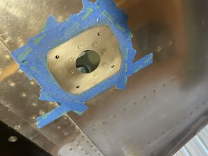
* 63/1000 2024T3 doubler, e.g. 4 x 4 inches<br>[[File:2023-09-24 18-29-54.jpg|267x267px]]<br>Builder made doubler example (Garmin doesn't provide template). | * 63/1000 2024T3 doubler, e.g. 4 x 4 inches<br>[[File:2023-09-24 18-29-54.jpg|267x267px]]<br>Builder made doubler example (Garmin doesn't provide template). | ||
* Optional: USB-B bulkhead debug connector (instead of Garmin pigtail part no 011-01782-00 which is just a coupling, not a bulkhead connector) at [https://www.amazon.com/gp/product/B071P2BGK5/ | * Optional: USB-B bulkhead debug connector (instead of Garmin pigtail part no 011-01782-00 which is just a coupling, not a bulkhead connector) at [https://www.amazon.com/gp/product/B071P2BGK5/ Amazon]<br>Color code: Black: GND (GHA-15 pin 20), Red: +5V (GHA-15 pin 19), White: D- (GHA-15 pin 10), Green: D+ (GHA-15 pin 9)<br>The wire will fit through a 1/4 inch snap bushing (before crimping the pins)<br>[[File:2023-10-05 20-15-48.jpg|250x250px]] | ||
* Optional: Suitable 10ft USB-C to USB-B laptop cable [https://www.amazon.com/gp/product/B082HQ3LP2 at Amazon] | |||
* Optional: Alodine pen to treat unpainted skin that will end up under the antenna: [https://www.aircraftspruce.com/catalog/cspages/touchprep.php?clickkey=92623 at Spruce].<br>[[File:2023-10-14 16-57-16.jpg|300x300px]] | |||
====Debug Data==== | |||
Garmin hasn't yet released a USB-driver for the GHA-15. However, after plugging the USB cable into a laptop, a new device enumerates named GHA-15 and the details show the serial number of the device which is proof enough that two-way communication can be established. | |||
[[File:Screen Shot 2023-11-06 at 6.29.08 PM.png|300x300px]] | |||
==== FCC Report ==== | ====FCC Report==== | ||
* [https://fccid.io/IPH-04099 FCC Record] | *[https://fccid.io/IPH-04099 FCC Record] | ||
Latest revision as of 03:18, 29 January 2024
Garmin GHA-15 Radar Altimeter
Intro
- The Garmin GHA-15 radar altimeter starts reporting altitude somewhere between 300 and 550 ft.
Note: the 500 ft announcement is GPS altitude based, 300 ft and lower is then radar altimeter based. - It transmits at 24 GHz with very low power (milliwatts) compared to COM radios and transponders (20 / 150 Watts). 24 GHz is not the controversial frequency that has interference issues with cell towers.
- It needs very little power and the connector accepts 22 AWG wire or thinner (you can transition to a 22 AWG lead wire near the connector if you want to run a thicker wire).
Videos
Threads
Installation Manual
- The G3X Touch installation manual covers the GHA-15.
Notepad

Connector
- Note: unlike with D-Sub connectors, each pin needs at least 5/8 inch of plain wire (22 AWG or thinner) before thickening up for example for a splice or shielding. The distance between the end of the pin and where the wire exists the rubber gasket through a tiny hole is quite long.
- Note: on the rubbery back side of the connector, the printed "1" seems to be closer to the hole to the left of the "1", but pin 1 is to the right of the "1".
The center pin 22 is a bit off-center to the bottom. Together with hole straight below it, they constitute the vertical center axis of the connector. At the two circles above, the center axis splits between 21/15 and 14/1. At the outermost circle at the bottom, it splits between 7/8. The 4 holes above 22 are almost in a perfect square pattern.
On the (hard) back-end of the connector, the numbers are printed in a way that the "1" is actually closer to pin "1".
(as seen from the back of the connector where you insert the pins through the silicone seals. The 9 o-clock position of this connector points forward in direction of flight.)


Screw Torque
- 10-32 Stainless steel: 33 in lb
Tools / Parts Needed
- K40 Positioner for DMC Crimper
- The 10-32 mounting screws are included. If you need more, those are MS51958-67, e.g. McMaster part number 91400A833 (pack of 25, same bolts needed for GPS antennas)
- 4 x 10-32 nut plates, e.g. K1000-3 / MS21047L3
- 63/1000 2024T3 doubler, e.g. 4 x 4 inches
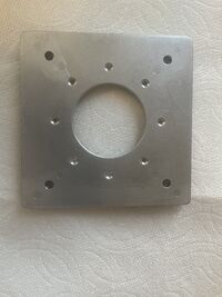
Builder made doubler example (Garmin doesn't provide template). - Optional: USB-B bulkhead debug connector (instead of Garmin pigtail part no 011-01782-00 which is just a coupling, not a bulkhead connector) at Amazon
Color code: Black: GND (GHA-15 pin 20), Red: +5V (GHA-15 pin 19), White: D- (GHA-15 pin 10), Green: D+ (GHA-15 pin 9)
The wire will fit through a 1/4 inch snap bushing (before crimping the pins)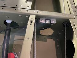
- Optional: Suitable 10ft USB-C to USB-B laptop cable at Amazon
- Optional: Alodine pen to treat unpainted skin that will end up under the antenna: at Spruce.


Debug Data
Garmin hasn't yet released a USB-driver for the GHA-15. However, after plugging the USB cable into a laptop, a new device enumerates named GHA-15 and the details show the serial number of the device which is proof enough that two-way communication can be established.
